ESYSFLOW — Project Tree Module
A comprehensive guide to understanding and working with the Project Tree workflow system
Table of Contents
- What is Project Tree?
- Overview
- Key Features
- Core Concepts
- User & Data Flow
- File Structure
- Important Functions & Data Movement
- Smart Numbering System
- Two-Way Synchronization
- State Management Overview
- Adding New Node Types
- System Architecture Diagram
What is Project Tree?
The Project Tree is a special sidebar in the esysflow application that helps you see, organize, and manage all the parts of your project in one place. Imagine it as a map or outline of your entire workflow, showing every step, sub-step, and connection. Each "flow" is like a folder, and each "node" is like a file or action inside that folder. The Project Tree updates automatically as you work, so you always have an up-to-date view of your project's structure.
In traditional workflow tools, you often have to choose between a visual canvas view or a hierarchical tree view. With Project Tree, you get both, and they work together seamlessly. The tree gives you the "big picture" organizational view, while the canvas gives you the detailed visual layout of how everything connects.
Key Metaphors:
- Flows = Top-level folders that contain your workflow logic
- Subflows = Nested folders for organizing related components
- Nodes = Individual files representing specific operations or data points
- Numbers = Automatically maintained order that reflects your workflow structure
It's always in sync with the Canvas, so what you see in the tree matches what you see in the main workspace. This helps you and your team stay organized and avoid mistakes.
Overview
Getting started with the Project Tree is simple. To add a new node, just right-click on any flow or subflow in the Project Tree, select the type of node you want from the searchable menu, and it will appear instantly in both the canvas and the tree. You can also drag nodes from the Library panel and drop them onto the canvas if you prefer a more visual approach.
The system is built on modular architecture with real-time bidirectional synchronization, automatic deduplication mechanisms, and smart numbering algorithms (position-based and topology-based). All logic flows through well-defined utilities and hooks for maintainability. State management uses React hooks with intelligent loop prevention through sync flags and deep equality checks.
Key Features
Right-Click Node Addition
You can add new nodes directly from the Project Tree by right-clicking on any flow or subflow. A searchable menu makes it easy to find the node type you need, speeding up your workflow. The system automatically calculates the canvas center point and places the node there, so you don't have to search for it.
Smart Numbering
Every node is automatically numbered based on its position or how it connects to other nodes. The system intelligently chooses between position-based numbering (top-to-bottom, left-to-right) and connection-based numbering (topological sort ensuring sources precede targets). This keeps your logic clear and easy to follow, even as your project grows.
Two-Way Sync
Any change you make in the tree is instantly reflected on the canvas, and vice versa. Changes propagate in both directions automatically: drag a node on the canvas and the tree updates, or right-click add in the tree and the canvas displays it. Intelligent flags prevent infinite update loops while maintaining consistency.
Drag & Drop
If you prefer, you can drag nodes from the Library and drop them directly onto the canvas at your exact desired position. This classic method is fully supported and works seamlessly with the Project Tree. The tree updates automatically to include whatever you just added.
Deduplication Logic
Prevents duplicate nodes from appearing in the tree, even when the same node participates in multiple flows or subflows. The system tracks node instances and displays them only once in the appropriate location.
Subflow Expansion
You can expand or collapse subflows in the tree to see or hide nested logic. This helps you focus on the parts of your project you're working on, without getting lost in details. Collapsed sections don't render their children, improving performance for large workflows.
Context Menus
Quick actions are always just a right-click away, letting you rename, delete, or add nodes and flows without searching through menus.
Core Concepts
Flows
Flows are top-level containers that represent major workflow segments. Each flow is visualized as a root-level item in the tree and can contain subflows and nodes. Think of them as folders that help you organize different phases or aspects of your simulation. For example, you might have a "Preprocessing Flow" for initial calculations, a "Main Analysis Flow" for core simulation, and a "Post-processing Flow" for results.
Subflows
Subflows are nested organizational units within flows. They help break down complex workflows into manageable chunks and can contain their own nodes and child subflows. You can nest subflows as deep as needed for your organization. A subflow inherits context from its parent flow, meaning it knows where it belongs in the hierarchy.
Nodes
Nodes are the atomic units of your workflow. Each node represents a specific operation, calculation, or data transformation. Nodes have a type that defines functionality (Vector, Scalar, etc.), a position for canvas placement, node-specific configuration data, and connections via edges linking to other nodes. When you add a node, you're adding a specific piece of functionality to your workflow.
Tabs
Tabs are workspaces that allow multiple canvas views within the same project. Each tab maintains its own set of nodes and edges, with the tree showing the active tab's structure. Switch between tabs to work on different workflow scenarios. Each tab stores its complete state including all nodes, edges, viewport position, and tab-specific configuration.
Edges
Edges are connections between nodes that define data flow and execution order. They represent dependencies or data passing between operations. Edges influence the smart numbering system by establishing dependency relationships. When nodes are connected, the numbering switches from position-based to topology-based automatically.
User & Data Flow
User Journey: Step by Step
This section explains how users interact with the Project Tree and how data moves through the system. Each action you take—like adding a node, dragging and dropping, or switching tabs—triggers a series of updates that keep the tree, canvas, and underlying data in sync.
A. Right-Click Add Node (Detailed Data Flow)
Step 1: User Interaction
You right-click on a flow or subflow in the Project Tree. This triggers handleContextMenu() in CustomTreeItem.tsx which captures mouse event coordinates and tree item context. The event passes to ProjectTree.tsx context menu controller, and the context menu opens at cursor position.
Step 2: Node Type Selection
You select a node type from the context menu. This triggers handleNodeTypeSelect() in useProjectTreeContextMenu.tsx which orchestrates the node creation pipeline. It calls createNodeDataFromRightClick() in rightClickUtils.ts to determine canvas center point and construct initial node data. The function returns a node data object containing { type, label, position, parentId, targetTabId }.
Step 3: Node Creation
With node data ready for processing, handleRightClickDrop() in flowDropHandler.ts is triggered. This creates a complete ReactFlow node object by adding a unique ID and merging default data from graph.json. The data transforms from node data to ReactFlow node format { id, type, position, data: {...} }.
Step 4: Tab State Update
The node gets added to the active tab through createSetNodesForTab() in useFlow.tsx. This updates the nodes array for the specific tab using immutable state operations. The tab data now reflects the new node in its internal storage.
Step 5: Canvas Synchronization
Tab data changes get detected by useCanvasEffects.ts (Effect 2: Tab → Canvas). This syncs updated tab data to ReactFlow canvas state. The isTabUpdate flag prevents circular updates, and the canvas visually displays the new node.
Step 6: Canvas State Propagation
Canvas state changes after the new node renders, triggering useCanvasEffects.ts (Effect 1: Canvas → Tab). This syncs ReactFlow state back to tab data storage. The isReactFlowUpdate flag plus deep equality check prevent loops, and tab storage updates with canvas-confirmed state.
Step 7: Tree Rebuild
With tab storage updated, buildTree() and mapTreeDataToTreeViewItems() in projectTreeUtils.ts get triggered. These reconstruct tree structure from updated nodes/edges, apply deduplication logic, and organize hierarchy. The Project Tree UI refreshes with the new node visible.
Step 8: Smart Numbering
Once the tree structure is finalized, either analyzePositionalHierarchy() or analyzeConnectionOrder() runs. The system chooses position-based numbering if no connections exist, or topology-based if nodes are connected. Node numbers update (like 1.1, 1.2, 2.1).
Data Movement Summary:
User Action → Event Handler → Context Menu State
    ↓
Node Type Selection → Node Data Object
    ↓
Node Data → ReactFlow Node Object → Tab Nodes Array
    ↓
Tab Nodes → Canvas Nodes (bidirectional sync)
    ↓
Canvas Nodes → Tree Structure → UI Update → Numbering
B. Drag & Drop Add Node (Data Flow)
Step 1: Drag Initiation
You drag a node from Library panel, triggering ReactFlow onDragStart event which stores node type in drag data.
Step 2: Drop on Canvas
You drop the node at your desired position, triggering ReactFlow onDrop handler in canvas.tsx. This captures drop coordinates, retrieves node type, and calls handleDrop() in flowDropHandler.ts.
Step 3: Node Creation
Node data gets prepared with drop position and creates ReactFlow node at exact drop location. The difference from right-click is that position is user-defined, not calculated.
Step 4-8: Identical to Right-Click Flow
Tab state update → Canvas sync → Tree rebuild → Numbering. Same functions, same data transformations. Result is node appears in tree with proper numbering.
C. Data Transformation Pipeline
Stage 1: User Selection
Input is user's node type choice (string). Function createNodeDataFromRightClick() outputs node data object:
{
  type: "vector",
  label: "Vector",
  position: { x: 400, y: 300 },
  parentId: "flow-123",
  targetTabId: "tab-1"
}
Stage 2: Node Construction
Input is node data object. Function handleRightClickDrop() outputs complete ReactFlow node:
{
  id: "node-abc-123",
  type: "vector",
  position: { x: 400, y: 300 },
  data: {
    label: "Vector",
    // ...default data from graph.json
  }
}
Stage 3: State Storage
Input is ReactFlow node object. Function createSetNodesForTab() outputs updated nodes array for tab.
Stage 4: Canvas Rendering
Input is tab nodes array. Function useCanvasEffects.ts outputs ReactFlow canvas state for visual rendering.
Stage 5: Tree Structure
Input is all nodes and edges from tabs. Function buildTree() outputs hierarchical tree structure with flows, subflows, and nodes properly nested.
Stage 6: UI Items
Input is tree structure. Function mapTreeDataToTreeViewItems() outputs UI-ready tree items (deduplicated, formatted).
D. Data Format Changes
At each stage, data changes format to fit its purpose:
| Stage | Data Format | Example |
|---|---|---|
| Node type selection | String | "Vector" |
| Node data object | Object | { type, label, position, parentId } |
| ReactFlow node | Object | { id, type, position, data } |
| Tab nodes array | Array | [node1, node2, ...] |
| Tree structure | Nested objects | { id, label, children: [...] } |
| TreeView items | UI objects | { id, label, type, children, ... } |
File Structure
The Project Tree module is organized into folders and files that separate different parts of the logic.
src/
  modules/
    canvas/
      components/
        canvas.tsx                           (Main canvas component, handles ReactFlow)
      hooks/
        useCanvasPage.ts                     (Page-level state management)
        useFlow.tsx                          (Tab and node/edge state management)
        useCanvasEffects.ts                  (Bidirectional sync orchestration)
      utils/
        flowDropHandler.ts                   (Node creation logic)
      widgets/
        sidebar/
          component/
            sidebar.tsx                      (Contains Library panel)
        projectTree/
          components/
            ProjectTree.tsx                  (Main tree container)
            CustomTreeItem.tsx               (Individual tree item with right-click)
            ProjectTreeContextMenu.tsx       (Context menu UI)
          hooks/
            useProjectTreeContextMenu.tsx    (Context menu logic)
          utils/
            projectTreeUtils.ts              (Tree building and deduplication)
            rightClickUtils.ts               (Right-click node creation utilities)
            positionalHierarchyAnalyzer.ts   (Position-based numbering)
            flowPositionAnalysis.ts          (Connection-based numbering)

public/
  data/
    library/
      graph.json                             (Node type definitions and defaults)
Key File Purposes:
canvas.tsx is the main canvas component where ReactFlow is initialized and configured. It handles the visual workspace, registers all node types, and manages canvas-level interactions.
useFlow.tsx is the source of truth for all tabs, nodes, and edges. It provides functions to create/update/delete nodes and edges, switch tabs, and manage tab lifecycle.
useCanvasEffects.ts orchestrates bidirectional synchronization between tab data and ReactFlow state, implementing loop prevention logic with flags and deep equality checks.
projectTreeUtils.ts contains tree building and deduplication logic. buildTree() constructs the hierarchical tree structure, and mapTreeDataToTreeViewItems() converts it to UI format.
graph.json contains node type definitions and defaults. When you create a new node, the system looks up its type in this file to get the defaults.
Important Functions & Data Movement
This table summarizes the main functions and files that make the Project Tree work.
| Function | File | Trigger | Purpose | Data In | Data Out |
|---|---|---|---|---|---|
| handleContextMenu() | CustomTreeItem.tsx | Right-click | Opens context menu | Mouse event | Context menu state |
| handleNodeTypeSelect() | useProjectTreeContextMenu.tsx | Node type select | Handles node type selection | Node type string | Node data object |
| createNodeDataFromRightClick() | rightClickUtils.ts | Node type select | Builds node data | Node type, context | Node data object |
| handleRightClickDrop() | flowDropHandler.ts | Node data ready | Creates new node | Node data object | ReactFlow node object |
| createSetNodesForTab() | useFlow.tsx | Node creation | Updates tab nodes | Node updater | Updated tab nodes |
| buildTree() | projectTreeUtils.ts | Tab data changes | Builds tree structure | Tabs, nodes | Tree structure |
| mapTreeDataToTreeViewItems() | projectTreeUtils.ts | Tree build | Converts to UI format | Tree structure | TreeView items |
| analyzePositionalHierarchy() | positionalHierarchyAnalyzer.ts | Tree rebuild | Position-based ordering | Nodes | Ordered node IDs |
| analyzeConnectionOrder() | flowPositionAnalysis.ts | Tree rebuild | Connection-based ordering | Nodes, edges | Ordered node IDs |
| useCanvasEffects | useCanvasEffects.ts | State change | Maintains sync | Nodes/edges/tabs | Synced state |
Smart Numbering System
The Smart Numbering System keeps your project organized by automatically assigning numbers to each node in your workflow. The system adapts to your workflow structure and updates in real-time as you work.
Position-Based Numbering
Used when nodes are spatially organized but not necessarily connected. The algorithm sorts nodes by Y-coordinate (top-to-bottom), then by X-coordinate within the same horizontal band (left-to-right). This is like reading a book - you read from top to bottom, left to right. Sequential numbers are assigned: 1.1, 1.2, 1.3, and so on.
Best for initial workflow design, parallel processing steps, and independent calculation blocks.
Connection-Based Numbering (Topological Sort)
Used when nodes are connected via edges, forming a dependency graph. The algorithm identifies source nodes (no incoming edges), traverses the graph following edge directions, and numbers nodes ensuring sources precede targets. It handles cycles gracefully with fallback ordering.
Best for sequential workflows, data transformation pipelines, and process flows with clear dependencies.
Automatic Selection
The system automatically chooses connection-based numbering if edges exist, otherwise uses position-based as fallback. You don't have to configure this - it just works.
Live Updates
Numbering recalculates instantly when nodes are moved on canvas, new connections are created, nodes are added or removed, or tree structure changes. The system debounces rapid changes to maintain performance.
Two-Way Synchronization
The bidirectional sync system ensures the Canvas and Project Tree are always in harmony. This section explains how this synchronization works and why it's complex.
How It Works
Canvas → Tabs (Effect 1)
When you modify the canvas (drag, connect, delete), this effect updates underlying tab storage. The isTabUpdate flag prevents updates during tab-initiated changes.
useEffect(() => {
  if (!isTabUpdate && hasChanges(canvasState, tabData)) {
    updateTabData(canvasState);
    setIsReactFlowUpdate(false);
  }
}, [canvasNodes, canvasEdges]);
Tabs → Canvas (Effect 2)
When tab switches or programmatic data changes occur, this effect updates canvas display. The isReactFlowUpdate flag prevents updates during canvas-initiated changes.
useEffect(() => {
  if (!isReactFlowUpdate && hasChanges(tabData, canvasState)) {
    setCanvasState(tabData);
    setIsTabUpdate(false);
  }
}, [activeTab, tabData]);
Loop Prevention
Without safeguards, updates would ping-pong infinitely: Canvas change → Tab update → Canvas update → Tab update → ∞. The solution uses update flags (isReactFlowUpdate and isTabUpdate) that mark the origin of changes, deep equality checks that only update if actual data differences exist, and flag resets after sync completes.
Edge Cases Handled
The system handles rapid user interactions (debouncing), tab switching during canvas operations, simultaneous multi-node operations, and undo/redo scenarios.
State Management Overview
The Project Tree module's state management is architected in layers, each with specific responsibilities.
State Layer Hierarchy:
Layer 1: useCanvasPage (Page-Level)
    ↓
Layer 2: useFlow (Tab & Workflow Data)
    ↓
Layer 3: useCanvasEffects (Synchronization)
    ↓
Layer 4: ReactFlow (Canvas Rendering)
Layer 1: useCanvasPage manages page-level concerns like which UI panels are open/closed, page-level settings, modal dialogs, and global loading states.
Layer 2: useFlow is the source of truth for all tabs, nodes, and edges. It maintains the array of all tabs, active tab ID, and provides functions to create/update/delete nodes and edges.
Layer 3: useCanvasEffects sits between tab storage and ReactFlow rendering. Its sole job is keeping them in sync using the two effects with flags to prevent loops.
Layer 4: ReactFlow is the ReactFlow library that handles all visual rendering and interaction. We feed it data through its API and it renders the canvas.
Critical State Variables:
- tabs: Array of all workspace tabs
- activeTabId: Currently displayed tab
- nodes: Current tab's node array
- edges: Current tab's edge array
- isReactFlowUpdate: Sync flag (Canvas → Tab)
- isTabUpdate: Sync flag (Tab → Canvas)
Adding New Node Types
Follow these steps to extend the system with custom node types.
Step 1: Define in graph.json
Add your node definition to public/data/library/graph.json:
{
  "nodes": [
    {
      "type": "customNode",
      "label": "Custom Node",
      "category": "custom",
      "defaultData": {
        "value": 0,
        "unit": "custom"
      }
    }
  ]
}
Step 2: Create Node Component (if custom UI needed)
// src/modules/canvas/nodes/CustomNode.tsx
export const CustomNode = ({ data }) => {
  return (
    <div className="custom-node">
      <Handle type="target" position={Position.Top} />
      {data.label}
      <Handle type="source" position={Position.Bottom} />
    </div>
  );
};
Step 3: Register Node Type
In canvas.tsx, register your node:
Step 4: Test
Right-click a flow in Project Tree, search for your node type in context menu, select and verify it appears on canvas and tree, test drag & drop from Library panel, and verify numbering updates correctly.
The system automatically adds it to the right-click context menu, makes it draggable from Library, includes it in tree structure, and applies smart numbering.
System Architecture Diagram
The complete system architecture showing user interactions, data transformations, and component relationships:
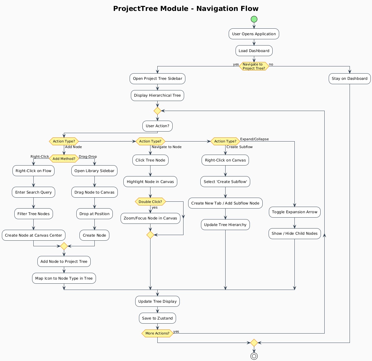
Diagram Overview:
This architecture diagram illustrates the complete flow from user interaction to visual rendering, including:
- Right-Click Node Addition Pipeline: Complete journey from context menu to node creation
- Drag & Drop Workflow: How drag events are captured and processed
- Bidirectional Synchronization: The two-way data flow between canvas and tree
- Tree Rebuild Process: How the tree structure is constructed and maintained